Free Vibration Analysis of Thin-Walled Box Beam of Crane Considering Distortion
-
摘要:
为了提高薄壁箱梁固有频率的计算精确度,基于广义坐标原理,对薄壁箱梁的动力特性进行了分析. 首先,通过虚功原理且考虑畸变形变的影响,获取了5种高度耦合模态(延伸、弯曲、扭转、翘曲和畸变)的自由振动微分方程组;其次,考虑转动惯性运动项的影响,建立了简支边界条件下的运动学模型,获得了薄壁箱形梁自由振动固有频率的四阶代数方程,进而求得固有频率的精确解;最后,通过算例将考虑畸变的固有频率精确解与Prokić 理论以及有限元分析方法的结果进行比较,验证了该方法的有效性和准确性. 结果表明:考虑畸变效应能够更准确地反映高阶状态下薄壁箱形梁的自由振动固有频率;对自由振动的4阶固有频率进行比较,当箱形梁长度为3 m时,本文理论的相对误差相较于Prokić 理论的0.42%下降至0.38%;当箱梁长度分别为4 m和5 m时,相对误差进一步下降至0.30% 和0.40%.
Abstract:In order to improve the calculation accuracy of the natural frequency of thin-walled box beams, the dynamic characteristics of thin-walled box beams are analyzed using the generalized coordinate principle. Firstly, the free vibration differential equations of five highly coupled modes (i.e., extension, bending, torsion, warping and distortion) are obtained by the virtual work principle and considering the influence of the distortion deformation. Secondly, considering the influence of the rotational inertial motion term, the kinematics model under the simply supported boundary condition is established. The fourth order algebraic equation of free vibration of the thin-walled box beam and the exact solution of the natural frequency are obtained. Finally, a numerical example is provided to compare the exact solution of natural frequency considering distortion with the results of Prokić theory and finite element analysis, so that the effectiveness and accuracy of present method are verified. The results show that when taking the distortion effect into consideration, the natural frequency of free vibration of the thin-walled box beam can be more accurately reflected in high-order modes. Comparison of natural frequencies at four orders of the free vibration indicates that when the length of the box girder is 3 m, the relative error of the present theory was reduced to 0.38% from Prokić’s 0.42%; when the length of the box girder is 4 and 5 m, the relative error can be further reduced to 0.30% and 0.40%, respectively.
-
Key words:
- bending /
- torsion /
- distortion /
- thin-walled box beam /
- free vibration
-
在起重机械中薄壁箱形梁在工程中得到了广泛的使用,在这些应用中减轻重量是非常重要的. 同时,由于这种结构的特点是高刚度重量比,且在静载荷和动载荷的作用下薄壁箱形梁对扭转和不稳定性都非常敏感. 薄壁箱形梁在反对称荷载作用下,除引起截面扭转外,还产生截面畸变. 在薄壁箱形结构设计中,传统方法仅考虑延伸、弯曲、扭转、翘曲4种位移形变,在高阶模态下,若不考虑畸变效应,将大大影响自由振动频率预测的准确度. 为了提高薄壁箱形梁结构的计算精度,根据结构力学特征建立广义位移模型,在原有基础上,增加畸变形变,这对薄壁箱形梁振动特性的研究具有重要的意义.
Gere等[1]采用Rayleigh-Ritz方法研究了各种边界条件下均布梁的弯扭耦合自由振动. 根据圣维南理论,Dokumaci等[2-3]在静载荷和动载荷作用下建立了一些存有扭转的模型. Ohga等[4]利用传递矩阵法研究了开、闭截面薄壁构件的自由振动. 此外,Adam[5]分析了单对称梁的耦合弯扭振动. Arpaci等[6-7]研究了任意截面梁的自由振动. 对于任意开口截面薄壁梁的振动,Jrad等[8]推导了不同边界条件下弯扭耦合模态的高自由振动模态的解析解. Gökdağ等[9]研究了单对称开截面梁的自由振动和受迫振动的弯扭耦合. 在模型中,由虚功原理导出了包含质量和刚度特性的动力刚度矩阵. Rafezy等[10]建立了三维非对称截面的复合材料梁弯曲运动的精确动力刚度矩阵. 李海超等[11]提出一种半解析法来分析圆柱壳结构自由振动特性. 蒲育等[12]基于扩展的N阶广义剪切变形梁理论获得弹性地基简支梁的自由振动精确解. Ovesy等[13]通过考虑不同的本构方程假设,对薄壁组合梁的自由振动特性进行了研究. Vo等[14]利用精剪变形理论对任意叠合梁进行了振动和屈曲分析. 该理论解释了剪切应变随梁高的抛物线变化,产生的耦合称为三耦合振动和屈曲. Filippi等[15]提出了一类用于组合结构静力和动力分析的新型精细化梁理论. 这些梁模型是通过对梁截面上位移场的3个分量执行切比雪夫多项式的高阶展开得到的. 考虑轴向翘曲效应和材料各向异性对壳壁中表面剪切应变的影响,Wang等[16]提出了一种精度较高的薄壁封闭截面组合梁结构动力学模型.
虽然一些文献对薄壁闭合梁进行了动力分析,但很少有文献考虑弯曲、扭转和畸变的耦合来求解薄壁闭合梁. 分析发现,薄壁箱梁的截面畸变对固有频率有显著影响. 因此,要正确地预测薄壁箱梁的动力特性,必须同时考虑弯曲、扭转和畸变形变. Kim等[17]就薄壁箱梁静力和动力进行了翘曲、扭转和畸变耦合变形的静力和动力特性分析. Kaya等[18]采用微分变换方法(DTM)分析轴向加载的闭口截面复合材料Timoshenko梁的自由振动响应,该梁的材料耦合特性是由于铺层方向的影响而发生弯曲和扭转振动. Kim [19]对在轴向力作用下组合梁的空间耦合进行了自由振动分析,利用能量原理推导出运动方程和力-位移关系方程,并基于位移分量的幂级数展开式给出位移参数的显式表达式. 基于能量法,Prokić等[20]利用Benscoter理论推导了薄壁梁的微分运动方程,研究了简支薄壁梁的自由振动行为. 但仅考虑到横向剪切变形、转动惯量及翘曲影响,假设了薄壁箱形梁板面完全刚性,即忽略了箱梁横截面的畸变形变. Dancila等 [21]提出了除非考虑薄壁箱形梁横截面畸变形变,否则无法准确预测更高的固有频率.
本文基于弹性力学理论,用能量法分析了简支薄壁箱形梁的自由振动. 考虑到弯曲、扭转和畸变的耦合作用,预测了薄壁箱形梁自由振动的固有频率和模态振型. 根据Benscoter理论,在广义位移的基础上,将各变形模态用广义坐标位移表示出来,进而求出薄壁箱形梁的固有频率和模态振型的精确显示公式. 该表达式简单明了,适合于一般的简支薄壁箱形梁理论的实际使用.
1. 动力学基本理论
1.1 基本假设
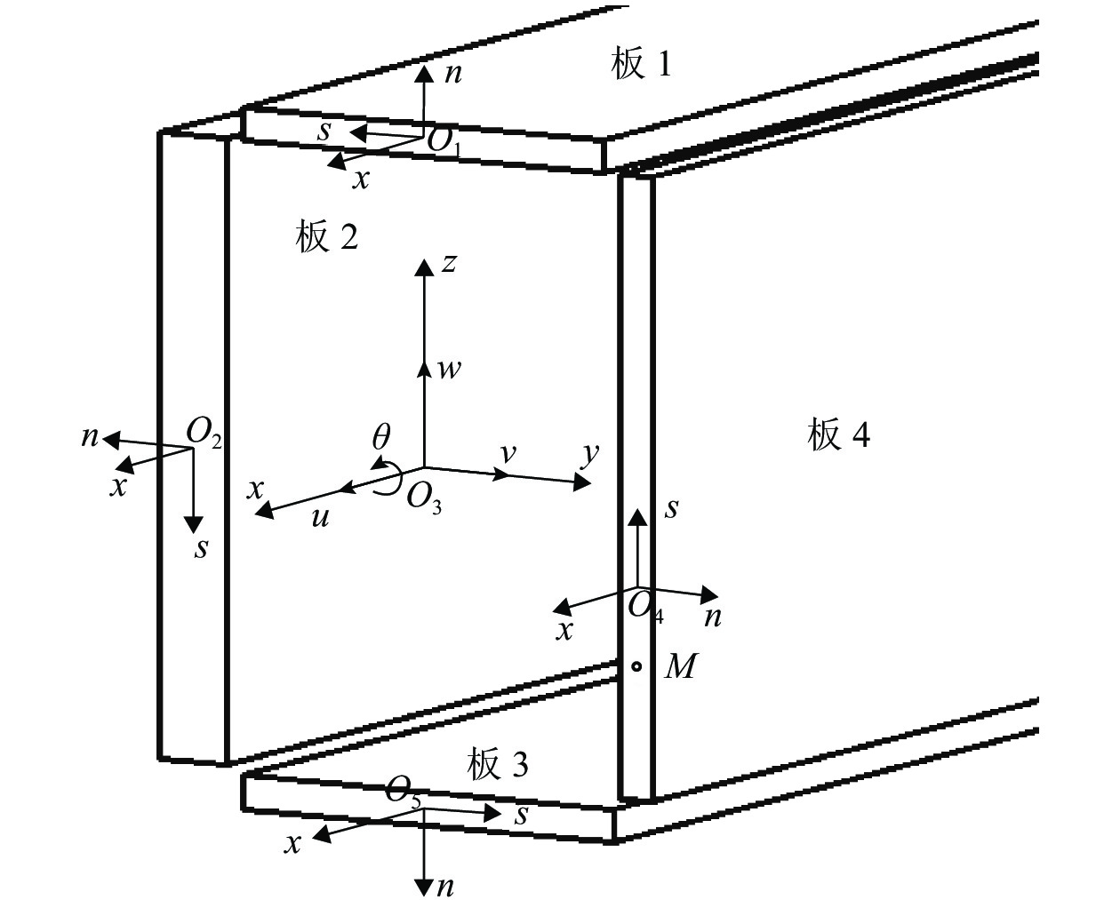
为了确定薄壁箱形梁的几何形状,使用了两个坐标系. 如图1所示. 图中:θ为扭转角. (x,y,z)为笛卡尔直角坐标系,其中,x轴与薄壁箱形梁的梁长重合,y轴和z轴与横截面的主轴重合. (n,s,x)为局部坐标系,其中,n为沿等值线(截面中线)测量的法向坐标,s为任意起始点沿等值线测量的剖面坐标. 点M(w,v,u)为横截面上任意一点,其中,v、w、u分别为y、z、x轴方向的位移. 薄壁箱形梁的理论基于以下假设:
1) 在各板中,中线平面沿轮廓线方向的线剪切应变分布与圣维南扭转的线剪切应变分布相同;
2) 假设薄壁箱形梁截面的中面轮廓不可延伸;
3) 变形量足够小,可采用线弹性理论.
1.2 运动学方程
根据薄壁箱形梁的静力屈曲分析[22]可以得出,薄壁箱形梁上以任意一点M为初始点的位移分量在小扭转的情况下,使用Vlasov模型产生的经典位移关系为
ui(s,n,x,t)=u(x,t)+Zi(s)w′(x,t)+Yi(s)v′(x,t)−ωi(s)θ′(x,t)−Ωi(s)χ′(x,t), (1) vi(s,n,x,t)=−ξ1v(x,t)−ξ2w(x,t)−hi(s)θ(x,t)+ηi(s,n)χ(x,t), (2) wi(s,n,x,t)=−ξ1w(x,t)−ξ2v(x,t)−sθ(x,t)+ψni(s)χ(x,t), (3) 式中:χ为畸变角;i = 1 ~ 4是箱梁各板的编号;ωi为扭转翘曲函数,如式(4);Ωi为畸变翘曲函数,如式(5);ηi、ψni分别为横截面y轴和z轴方向的畸变位移,如式(6)、(8);t为时间;Zi(s)、Yi(s)、hi(s)均为横截面系数,分别如式(9) ~ (11);
ξ1 、ξ2 分别如式(12)、(13).ωi(s)=[ξ22(b2+ξ2y0)−ξ21(h2+ξ2z0)]s, (4) Ωi(s)=∫s0ψsi(s)ds, (5) ηi(s,n)=ψsi(s)+n∂ψni(s)∂s, (6) ψsi(s)=dZi(s)dsYi(s)−dYi(s)dsZi(s), (7) ψni(s)=(−Lside2+3Lsides2−2L2sides3)(−1)i+1κ, (8) κ={2b/(b+h),i=1,3,2h/(b+h),i=2,4, Zi(s)=ξ2(h2+ξ1z0)+ξ2s, (9) Yi(s)=ξ2(b2+ξ2y0)−ξ1s, (10) hi(s)=ξ21(h2+ξ1z0)+ξ22(b2+ξ2y0), (11) ξ1=1+(−1)i+12(2−i), (12) ξ2=1+(−1)i2(i−3), (13) 式(4) ~ (13)中:b和h分别为箱梁横截面的宽和高;(z0, y0)为横截面的剪切中心;Lside为箱梁横截面各边相对应的长度.
根据Kim等[17]理论研究,横截面畸变形变的几何系数ψsi(s)可满足主要的静、动平衡条件. 此外,当每个板是不等厚时,κ是不连续的.
本文重点研究薄壁箱形梁在动载荷作用下的行为. 因此,在自由振动和线性动力学框架下,用式(1) ~ (3)作为运动学方程是充分、有效的. 为此需要对应变、动能和外载荷进行分析,进而推导运动控制方程. 应变能U的微分为
δU=4∑i=1∫∬(σxiδεxi+τsiδγsi)dFidx, (14) 式中:σxi和τsi为薄壁箱形梁的正应力和切应力分量;εxi和
γsi 分别为正应变和剪切应变,分别如式(15)、(16);Fi为各板的面积;L为梁长.εxi=u′0+Zi(s)w″ (15) \begin{split} &\gamma _{si}^{} = - \left( {{{h}{'} _i}(s) + \partial {{\omega}{'} _i}(s)} \right)\theta {'}+\\ &\quad\left( {{{\eta }{'} _i}(s,n) + {{\varOmega }{'} _i}(s)} \right)\chi {'}, \end{split} (16) 式中:u0、w0、v0分别为任意点M在u、w、v方向的初始位移.
应变能的变化可以用薄壁单元截面上的内力函数表示. 在动力学系统变分原理的基础上,推导动力学运动方程. 根据式(14)对横截面进行积分后,应变能可表示为
\begin{split} &\delta U = \int_L (N \text{δ} u' + {M_{\textit{z}}}\text{δ} v'' - {M_y}\text{δ} w'' + {B_{\omega \theta }}\text{δ} \theta '' + \\ &\quad {B_{\omega \chi }}\text{δ} \chi '' + {M_{sv}}\text{δ} \theta ' + {M_{sv\chi }}\text{δ} \chi {'} ){\rm{d}}x, \end{split} (17) 式中:N为轴向力;My和Mz分别为关于y轴和z轴的弯矩;Bωθ为双力矩;Bωχ为畸变引起的双力矩;Msv为圣维南扭矩;Msvχ为畸变引起的扭矩. 具体如式(18)所示.
\left\{ { \begin{array}{l} N = \displaystyle\sum\limits_{i = 1}^4 {\iint {{\sigma _{xi}}}{\rm{d}}{F_i}} ,\\ {M_y} = \displaystyle\sum\limits_{i = 1}^4 {\iint {{\sigma _{xi}}{{\textit{Z}}_i}(s)}{\rm{d}}{F_i}} ,\\ {M_{\textit{z}}} = - \displaystyle\sum\limits_{i = 1}^4 \iint{{\sigma _{xi}}{Y_i}(s) {\rm{d}}{F_i}} ,\\ {B_{\omega \theta }} = -\displaystyle\sum\limits_{i = 1}^4 {\iint {{\sigma _{xi}}{\omega _i}(s)}} {\rm{d}}{F_i}, \\ {B_{\omega \chi }} = - \displaystyle\sum\limits_{i = 1}^4 {\iint {{\sigma _{xi}}}{\varOmega _i}(s){\rm{d}}{F_i}} ,\\ {M_{sv}} = \displaystyle\sum\limits_{i = 1}^4 {\iint{{\tau _{xsi}}({h_i}(s) + \partial {\omega _i}(s)){\rm{d}}{F_i}}} ,\\ {M_{sv\chi }} = \displaystyle\sum\limits_{i = 1}^4 {\iint {{\tau _{xsi}}({\eta _i}(s,n) - {{\varOmega '}_i}(s)){\rm{d}}{F_i}}}. \end{array} } \right. (18) 2. 运动控制方程
在能量原理的基础上,应用哈密顿理论推导运动控制方程. 箱梁总能量的微分可由应变能U、动能T和外载荷功W表示,如式(19).
\text{δ} \int_{{t_1}}^{{t_2}} {(U - T - W)} {\rm{d}}t = 0 , (19) 式中:t1和t2分别为起、止时间.
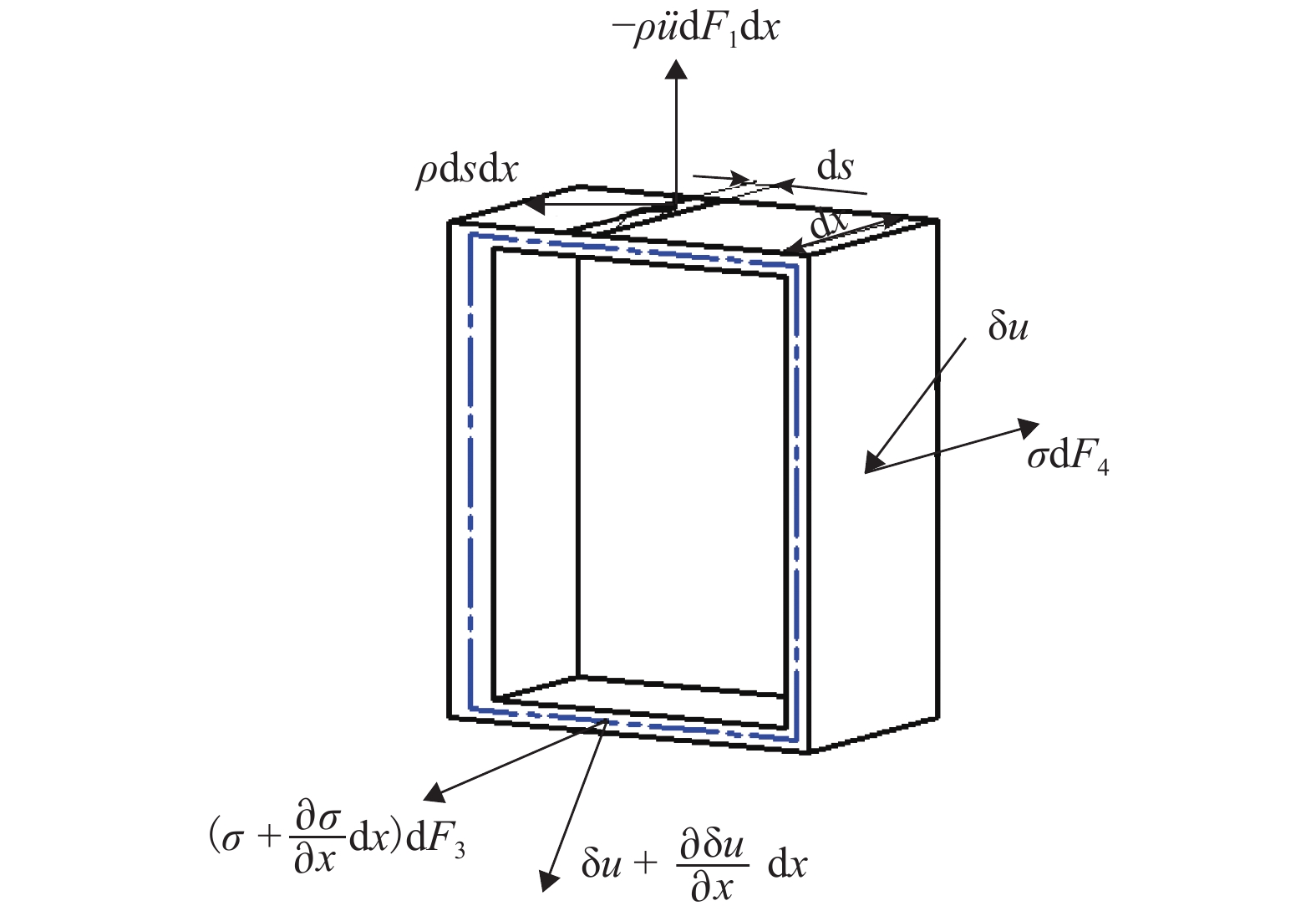
利用虚位移原理可以得到薄壁箱形梁的运动方程. 图2中考虑了横截面x1=x和x2 = x + dx之间的一个小单元,在中面上承受单位面积上的外载荷p(px, py, pz),其中:
{p_x}、\,{p_y}、\, {p_{\textit{z}}} 分别为x、y、z单位面积上的外载荷.图2中:ρ为单位体积质量密度. 在横截面上作意一点的应力为\textit{σ} =-{\tau _{xs}}\sin\; \alpha + {\tau _{xs}}\cos\; \alpha + {\sigma _x} , (20) 式中:α为轮廓中线的法线与x轴之间的夹角;
{\tau _{xs}} 为切应力.虚位移δu满足必要的连续性条件和位移边界条件,可以采用与实位移向量相同的形式. 根据虚位移原理,虚位移可表示为
\begin{split} &\text{δ} {u}= \text{δ} {v} + \text{δ} w + \text{δ} u = \\ &\quad -\xi_{1i} \text{δ} w-\xi_{2i} \text{δ} v-s \text{δ} \theta + \psi_{{\rm{n}}i}(s) \text{δ} \chi + \\ &\quad -\xi_{1i} \text{δ} v-\xi_{2i} \text{δ} w-h_{i}(s) \text{δ} \theta+\\ &\quad \eta_{i}(s, n) \text{δ} \chi + \text{δ} u + {\textit{z}}_{i}(s) \text{δ} w^{\prime}+\\ &\quad Y_{i}(s) \text{δ} v^{\prime}-\omega_{i}(s) \text{δ} \theta^{\prime}-\varOmega_{i}(s) \text{δ} \chi^{\prime}. \end{split} (21) 加速度矢量可以表示为
\begin{split} & \text{δ} \ddot{{u}}=\text{δ} \ddot{{v}} + \text{δ} \dddot{w} + \text{δ} \ddot{u}=\\ &\quad -\xi_{1i}{} \text{δ} \ddot{w}-\xi_{2i} \text{δ} \ddot{v}-s \text{δ} \ddot{\theta} + \psi_{{\rm{n}}i}(s) \text{δ} \ddot{\chi} + \\ &\quad -\xi_{1i} \text{δ} \ddot{v}-\xi_{2i} \text{δ} \ddot{w}-h_{i}(s) \text{δ} \ddot{\theta} + \eta_{i}(s, n) \text{δ} \ddot \chi +\\ &\quad \text{δ} \ddot{u} + {\textit{z}}_{i}(s) \text{δ} \frac{{{\partial ^3}u}}{{\partial {t^3}}}\frac{{\partial u}}{{\partial x}} + Y_{i}(s) \text{δ} \frac{{{\partial ^2}v}}{{\partial {t^2}}}\frac{{\partial v}}{{\partial x}}-\\ &\quad \omega_{i}(s) \text{δ} \frac{{{\partial ^2}\theta }}{{\partial {t^2}}}\frac{{\partial \theta }}{{\partial x}}-\varOmega_{i}(s) \text{δ} \frac{{{\partial ^2}\chi}}{{\partial {t^2}}}\frac{{\partial \chi}}{{\partial x}} . \end{split} (22) 等质量密度薄壁箱形梁单元的动能为
T = \frac{1}{2}{\int \iint {\rho \left[{{\left(\frac{{\partial u}}{{\partial t}}\right)}^2} + {{\left(\frac{{\partial v}}{{\partial t}}\right)}^2} + {{\left(\frac{{\partial w}}{{\partial t}}\right)}^2}\right]} } {\rm{d}}F_i{\rm{d}}x. (23) 动能的微分表示为
\text{δ} T = \rho \iint {\ddot u}\text{δ} u{\rm{d}}F_i. (24) 根据能量原理,薄壁箱形梁单元单位长度外载荷和惯性力的虚功为
\text{δ} W=\iint\left(\textit{σ}^{\prime} \text{δ} {u} + \sigma \text{δ} {u}^{\prime}\right) {\rm{d}} F_i + \int_{} \overline{{p}} \text{δ} {u} {{\rm{d}}} s, (25) 式中:
\overline{{p}} 为惯性力.经整理计算,应用虚位移原理,可获得关于虚位移参数δu0、δv0、δw0、δθ、δχ的方程,对于任意虚位移参数均能恒等地满足这些方程,即虚位移参数的系数表达式必须消失. 将式(17)代入式(18),可以得到控制方程和相关的边界条件,则关于延伸、弯曲、扭转和畸变耦合的方程为
N^{\prime}-\rho \iint \ddot{u} \mathrm{ ~ d} F_i + p_{x}=0, (26) \left\{ \begin{array} {l} M_{{\textit{z}}}^{\prime \prime} + \rho \iint Y_i(s) u^{\prime} \mathrm{d} F_i + \rho \iint \ddot{v} \mathrm{ ~ d} F_i-p_{y} + m_{{\textit{z}}}^{\prime}=0,\\ M_{y}^{\prime \prime}-\rho \iint {\textit{Z}}_i(s) u^{\prime} \mathrm{d} F_i-\rho \iint \ddot{u} \mathrm{ ~ d} F_i + p_{{\textit{z}}} + m_{y}^{\prime}=0, \end{array} \right. (27) \begin{split} & \rho \iint \left\{ {\omega \frac{{{\partial ^2}u}}{{\partial {t^2}}}\frac{{\partial u}}{{\partial x}}} - {\left[({\textit{Z}}_i(s) - {{\textit{z}}_0})\ddot v - (Y_i(s) - {y_0})\ddot w\right]} \right\}{\rm{d}}F_i+ \\ & \quad {B''_{\omega \theta }}-{M'_{sv}} - {m_p} - {m_\omega } = 0, \end{split} (28) \begin{split} & \rho \iint{\left[\varOmega_i (s)\frac{{{\partial ^2}u}}{{\partial {t^2}}}\frac{{\partial u}}{{\partial x}}+{{\eta }_{i}}(s,n)\ddot{v}-\psi _{{\rm{n}}i}(s)\ddot{w}\right]}{\rm{d}}F_i+ \\ &\quad {{{{B}_{\omega \chi }''}}}-{{{{M}_{sv\chi }'}}}-{{m}_{p\chi }}-{{m}_{\varOmega }}=0 , \end{split} (29) 式中:mz和my分别为单位长度外力引起的关于z轴和y轴的弯矩;mp和mω分别为单位长度外力引起扭矩和双力矩;mpχ和mΩ分别为单位长度外力引起畸变扭矩和畸变双力矩.
式(26) ~ (30)是薄壁箱形梁延伸、弯曲、扭转和畸变的自由振动的最一般形式,变量u、v、w、θ、χ是完全耦合的.
对于具有连续质量分布且结构形式简单的结构可采用广义位移法. 对于简支梁,设任意时间t的任一截面的位移可用三角函数表示为
\left[\begin{array}{l} v(x, t)\\ w(x, t)\\ \theta(x, t)\\ \chi(x, t) \end{array}\right]=\left[\begin{array}{c} V(x)\\ W(x)\\ \varTheta(x)\\ X(x) \end{array}\right] \sin \;\omega t , (30) 式中:V(x)、W(x)、Θ(x)、Χ(x)分别为横向位移、纵向位移、扭转和畸变的振幅,如式(31).
\left[ {\begin{array}{*{20}{c}} {V(x)} \\ {W(x)} \\ {\varTheta (x)} \\ {{\rm X}(x)} \end{array}} \right] = \left[ {\begin{array}{*{20}{c}} {{C_V}} \\ {{C_W}} \\ {{C_\varTheta }} \\ {{C_{X}}} \end{array}} \right]\sin\; {\lambda _k}, (31) 式中:
\sin\; {\lambda _k} 为满足位移边界条件的振动模态函数,其中,{\lambda _k} =kπx/L,为形状函数, k=1,2,3,…;CV、CW、CΘ、CΧ均为常数.在简支梁的情况下,各支点处的支撑为防止旋转和可自由弯曲,其边界条件为
\left[\begin{array}{l} V(x) \\ W(x) \\ \varTheta(x) \\ X(x) \end{array}\right]=\left[\begin{array}{l} 0 \\ 0 \\ 0 \\ 0 \end{array}\right],\;\;\left[\begin{array}{l} V^{\prime \prime}(x) \\ W^{\prime \prime}(x) \\ \varTheta^{\prime \prime}(x) \\ X^{\prime \prime}(x) \end{array}\right]=\left[\begin{array}{l} 0 \\ 0 \\ 0 \\ 0 \end{array}\right]. (32) 为了求出CV、CW、CΘ、CΧ为非零解,式(30) ~ (32)的导数必须为0,即
\left[ {\begin{array}{*{20}{c}} {{I_y}\lambda _{{k}}^4 - {\omega _*}(\lambda _{k}^2{I_y} + A)}&0&{ - {{\textit{z}}_0}A{\omega _*}}&{{A_1}{\omega _*}} \\ 0&\begin{gathered} {I_{\textit{z}}}\lambda _{{k}}^4 \\ - {\omega _*}(\lambda _{{k}}^2{I_{\textit{z}}} + A) \\ \end{gathered} &{{y_0}A{\omega _*}}&{ - {A_2}{\omega _*}} \\ { - {y_0}A({I_{\omega \theta }}\lambda _{{k}}^2 + 1){\omega _*}}&{{{\textit{z}}_0}A({I_{\omega \theta }}\lambda _{{k}}^2 + 1){\omega _*}}&{ {I_{\omega \theta }}\lambda _{{k}}^4 + G/E{I_{\rm{t}}}\lambda _{{k}}^2 + ({I_{\rm{p}}} - {I_{\omega \theta }}\lambda _{{k}}^2){\omega _*} }&0 \\ {({A_1} + {A_3}\lambda _{{k}}^2){\omega _*}}&{ - ({A_2} + {A_4}\lambda _{{k}}^2){\omega _*}}&0&{ {I_{\omega \chi }}\lambda _{{k}}^4 + G/E{I_{\rm{d}}}\lambda _{{k}}^2 + ({I_{{\rm{p}}\chi }} - {I_{\omega \chi }}\lambda _{{k}}^2){\omega _*} } \end{array}} \right] = 0 , (33) 式中:
{\omega _ * } = \dfrac{\rho }{E}{\omega ^2} ,E为弹性模量;G为剪切模量;Iy和Iz分别为关于y、z轴的惯性矩;It和Iωθ分别为圣维南扭转和翘曲常数;Id和Iωχ分别为畸变引起的扭转和翘曲常数;Ip为扭转和翘曲耦合惯性矩;Ipχ为畸变与翘曲耦合惯性矩;A为横截面面积;A1、A2分别为纵向、横向弯曲与畸变耦合惯性矩参数;A3、A4分别为纵向、横向弯曲与翘曲耦合惯性矩参数.经整理可得四阶频率代数方程为
a \omega_{*}^{4} + c \omega_{*}^{3} + d \omega_{*}^{2} + e\omega_{*} + f=0 \text{,} (34) 式中:a、c、d、e和f均为常数.
3. 算例分析
3.1 畸变模态下薄壁箱形梁的自由振动(算例1)
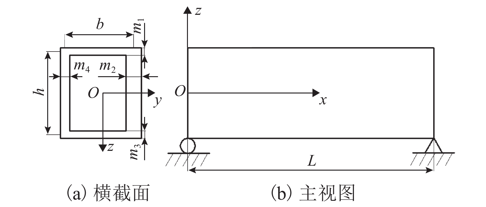
为了验证理论公式(式(34))的正确性,求解薄壁箱形梁在畸变模态下自由振动时的频率和振型,并与有限元分析(ANSYS)结果进行对比. 图3为简支薄壁箱形梁的几何参数. 通过对薄壁箱梁的模态分析,验证该方法的有效性和准确性. 该梁的材料参数和几何参数为:E = 210 GPa,G = 80.7 GPa,ρ = 7 850 kg/m3,b = 150 mm,h = 200 mm. 薄壁箱形梁的板厚为:m1 = m3 = 4 mm,m2 = 8 mm,m4 = 5 mm. 在有限元分析过程中,ANSYS软件中采用4node181的壳单元进行分析,在网格划分后生成1932个节点和1890个单元.
表1为考虑横截面畸变形变的理论方法和有限元分析方法下薄壁箱形梁其中的4阶模态(2、4、6、8阶)的固有频率对比. 为了对结果进行评估,将有限元法的固有频率表示为ωFEA,本方法的固有频率表示为ω1, Δ为本理论的固有频率与有限元固有频率的相对误差.
表 1 薄壁箱形梁其中4阶的固有频率比较Table 1. Comparison of 2-, 4-, 6-, and 8-order natural frequencies of thin-walled box beams阶数 ω1/Hz ωFEA/Hz Δ/% 2 9.36 9.34 0.18 4 36.99 36.90 0.25 6 54.30 54.11 0.36 8 89.46 88.67 0.89 由表1可以看出:固有频率结果具有较强的一致性,其中最大误差为0.89%(在第8阶时),验证了本文分析方法可以较准确地进行薄壁箱形梁固有频率的预测;伴随着模态阶数的升高,固有频率的误差逐渐增加.
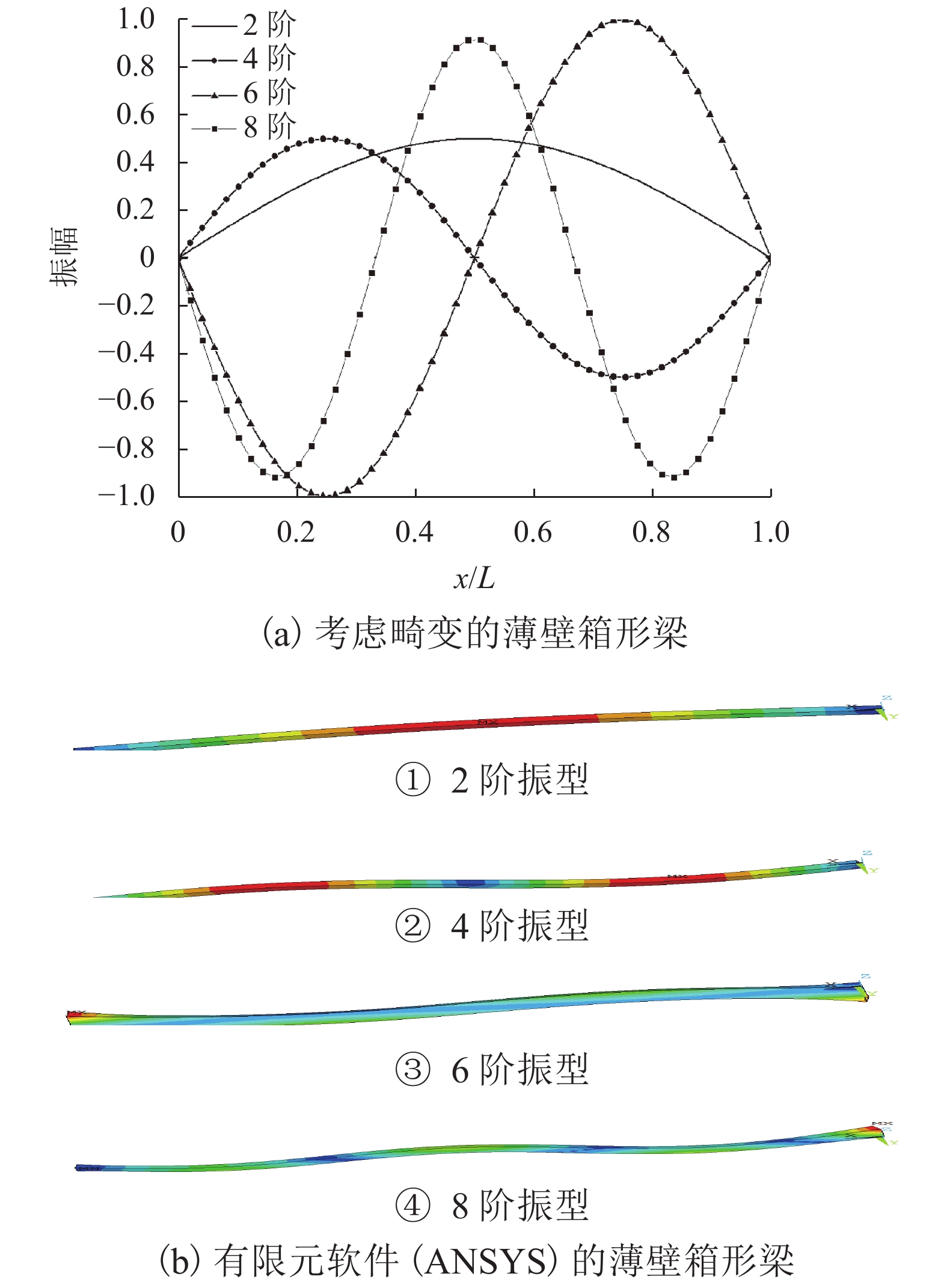
图4为2、4、6阶和8阶的弯曲模态振型.
由图4可以看出:薄壁箱形梁的所有振型均为傅立叶变换,所得到的弯曲模态振型与ANSYS弯曲模态振型结果吻合良好.
3.2 不同长度对自由振动的影响(算例2)
为了研究畸变形变对薄壁箱梁自由振动特性的影响,考虑了3种不同长度的结构. 将本文的计算结果与Prokić等[20]的弯扭耦合(不考虑畸变形变)情况下求解的自由振动的精确解进行对比分析. 薄壁箱形梁的材料参数和几何参数与算例1相同. 表2为箱梁长度分别为3、4、5 m时薄壁箱形梁的前4阶自由振动频率及其相对误差. Prokić方法计算的弯扭组合结果用ω1表示;考虑畸变形变的相关结果用ω2表示;Δ1为Prokić 结果与有限元分析法的自由振动频率的相对误差;Δ2为考虑畸变形变情况下的自由振动频率与有限元分析法的自由振动频率的相对误差.
表 2 简支薄壁箱形梁的固有频率Table 2. Natural frequencies of simply supported thin-walled box beamsL/m 阶数 ω1/Hz ω2/Hz ωFEA/Hz Δ1/% Δ2/% 3 1 11.92 11.91 11.91 0.06 0 2 63.16 63.12 63.03 0.20 0.14 3 64.90 64.08 64.67 0.35 0.20 4 114.41 114.36 113.93 0.42 0.38 4 1 7.33 7.33 7.33 0 0 2 36.87 36.86 36.83 0.10 0.08 3 50.04 50.01 49.91 0.26 0.20 4 76.63 76.57 76.34 0.38 0.30 5 1 5.11 5.11 5.11 0 0 2 25.79 25.79 25.77 0.08 0.06 3 35.72 35.71 35.64 0.23 0.19 4 61.68 61.64 61.47 0.34 0.28 在表2 中,将ω1与ωFEA进行比较,可以看出:本方法的解与有限元方法的结果有较强的一致性,且准确性和有效性较高,尤其是在第4阶模态情况下,最大相对误差Δ2仅为0.38%(当L=3 m);与Prokić 方法相比,自由振动频率ω1 < ω2,即考虑畸变形变可有效降低自由振动频率,进而提高了自由振动数值精确解的有效值;长细比越大,自振频率越小;在高阶模态下考虑畸变时的固有频率更接近于有限元法的解,因此,在高阶模态上考虑畸变效应的振动分析更占优势.
4. 结 论
考虑畸变效应的耦合位移模态特征,提高了预测自由振动的准确度,有利于薄壁箱形梁的设计和性能分析. 得到如下结论:
1) 推导出包含轴向延伸、弯曲、翘曲、扭转和畸变的运动学高耦合强度的控制方程.
2) 考虑畸变形变的模态振型与有限元分析结果吻合较好. 前4阶模态情况下最大相对误差仅有0.38%(当L=3 m时).
3) 与Prokić方法相比,考虑畸变效应情况下,自由振动频率可以得到有效降低,提高了自由振动数值精确解的有效值.
-
表 1 薄壁箱形梁其中4阶的固有频率比较
Table 1. Comparison of 2-, 4-, 6-, and 8-order natural frequencies of thin-walled box beams
阶数 ω1/Hz ωFEA/Hz Δ/% 2 9.36 9.34 0.18 4 36.99 36.90 0.25 6 54.30 54.11 0.36 8 89.46 88.67 0.89 表 2 简支薄壁箱形梁的固有频率
Table 2. Natural frequencies of simply supported thin-walled box beams
L/m 阶数 ω1/Hz ω2/Hz ωFEA/Hz Δ1/% Δ2/% 3 1 11.92 11.91 11.91 0.06 0 2 63.16 63.12 63.03 0.20 0.14 3 64.90 64.08 64.67 0.35 0.20 4 114.41 114.36 113.93 0.42 0.38 4 1 7.33 7.33 7.33 0 0 2 36.87 36.86 36.83 0.10 0.08 3 50.04 50.01 49.91 0.26 0.20 4 76.63 76.57 76.34 0.38 0.30 5 1 5.11 5.11 5.11 0 0 2 25.79 25.79 25.77 0.08 0.06 3 35.72 35.71 35.64 0.23 0.19 4 61.68 61.64 61.47 0.34 0.28 -
[1] GERE J M, LIN Y K. Coupled vibrations of thin-walled beams of open cross section[J]. Journal of Applied Mechanics, 1958, 25(3): 373-378. doi: 10.1115/1.4011830 [2] DOKUMACI E. An exact solution for coupled bending and torsion vibrations of uniform beams having single cross-sectional symmetry[J]. Journal of Sound and Vibration, 1987, 119(3): 443-449. doi: 10.1016/0022-460X(87)90408-1 [3] FRIBERG P O. Coupled vibrations of beams−an exact dynamic element stiffness matrix[J]. International Journal for Numerical Methods in Engineering, 1983, 19(4): 479-493. doi: 10.1002/nme.1620190403 [4] OHGA M, TAKAO H, HARA T. Natural frequencies and mode shapes of thin-walled members[J]. Computers & Structures, 1995, 55(6): 971-978. [5] ADAM C. Forced vibrations of elastic bending-torsion coupled beams[J]. Journal of Sound and Vibration, 1999, 221(2): 273-287. doi: 10.1006/jsvi.1998.2005 [6] ARPACI A, BOZDAG E. On free vibration analysis of thin-walled beams with nonsymmetrical open cross-sections[J]. Computers & Structures, 2002, 80(7/8): 691-695. [7] TANAKA M, BERCIN A N. Free vibration solution for uniform beams of nonsymmetrical cross section using Mathematica[J]. Computers & Structures, 1999, 71(1): 1-8. [8] JRAD W, MOHRI F, ROBIN G, et al. Analytical and finite element solutions of free and forced vibration of unrestrained and braced thin-walled beams[J]. Journal of Vibration and Control, 2020, 26(5/6): 255-276. [9] GÖKDAĞ H, KOPMAZ O. Coupled bending and torsional vibration of a beam with in-span and tip attachments[J]. Journal of Sound and Vibration, 2005, 287(3): 591-610. doi: 10.1016/j.jsv.2004.11.019 [10] RAFEZY B, HOWSON W P. Exact dynamic stiffness matrix for a thin-walled beam of doubly asymmetric cross-section filled with shear sensitive material[J]. International Journal for Numerical Methods in Engineering, 2007, 69(13): 2758-2779. doi: 10.1002/nme.1864 [11] 李海超,庞福振,李玉慧,等. 复杂边界条件圆柱壳自由振动特性分析[J]. 振动工程学报,2020,33(1): 56-63.LI Haichao, PANG Fuzhen, LI Yuhui, et al. Free vibration characteristics analysis of circular cylindrical shell under complex boundary conditions[J]. Journal of Vibration Engineering, 2020, 33(1): 56-63. [12] 蒲育,周凤玺. 基于一种广义梁理论的弹性地基FGM简支梁自由振动解析解[J]. 应用力学学报,2020,37(2): 840-845,946.PU Yu, ZHOU Fengxi. Exact solutions for free vibration of FGM simply supported beams on elastic foundation based on a generalized beam theory[J]. Chinese Journal of Applied Mechanics, 2020, 37(2): 840-845,946. [13] OVESY H R, KHANEH MASJEDI P. Investigation of the effects of constitutive equations on the free vibration behavior of single-celled thin-walled composite beams[J]. Mechanics of Advanced Materials and Structures, 2014, 21(10): 836-852. doi: 10.1080/15376494.2012.725266 [14] VO T P, THAI H T. Vibration and buckling of composite beams using refined shear deformation theory[J]. International Journal of Mechanical Sciences, 2012, 62(1): 67-76. doi: 10.1016/j.ijmecsci.2012.06.001 [15] FILIPPI M, PAGANI A, PETROLO M, et al. Static and free vibration analysis of laminated beams by refined theory based on Chebyshev polynomials[J]. Composite Structures, 2015, 132: 1248-1259. doi: 10.1016/j.compstruct.2015.07.014 [16] WANG S, ZHANG C. Structure mechanical modeling of thin-walled closed-section composite beams, part 2: multi-cell cross section[J]. Composite Structures, 2014, 113: 56-62. doi: 10.1016/j.compstruct.2014.03.002 [17] KIM Y Y, KIM J H. Thin-walled closed box beam element for static and dynamic analysis[J]. International Journal for Numerical Methods in Engineering, 1999, 45(4): 473-490. doi: 10.1002/(SICI)1097-0207(19990610)45:4<473::AID-NME603>3.0.CO;2-B [18] KAYA M O, OZGUMUS O O. Flexural-torsional-coupled vibration analysis of axially loaded closed-section composite Timoshenko beam by using DTM[J]. Journal of Sound and Vibration, 2007, 306(3/4/5): 495-506. [19] KIM N I. Dynamic stiffness matrix of composite box beams[J]. Steel and Composite Structures, 2009, 9(5): 473-497. doi: 10.12989/scs.2009.9.5.473 [20] PROKIĆ A, LUKIĆ D. Dynamic analysis of thin-walled closed-section beams[J]. Journal of Sound and Vibration, 2007, 302(4/5): 962-980. [21] DANCILA D S, ARMANIOS E A, LENTZ W K. Free vibration of thin-walled closed-section composite beams with optimum and near-optimum coupling[J]. Journal of Thermoplastic Composite Materials, 1999, 12(1): 2-12. doi: 10.1177/089270579901200101 [22] TAN M Y, CHENG W M. Non-linear lateral buckling analysis of unequal thickness thin-walled box beam under an eccentric load[J]. Thin-Walled Structures, 2019, 139: 77-90. doi: 10.1016/j.tws.2019.02.028 -