• ISSN 0258-2724
  • CN 51-1277/U
  • EI Compendex
  • Scopus
  • Indexed by Core Journals of China, Chinese S&T Journal Citation Reports
  • Chinese S&T Journal Citation Reports
  • Chinese Science Citation Database
FU Shanqiang, WU Donghua, HAN Weitao, ZHOU Ying. Modeling and Analysis of High-Speed Maglev Electromagnets Based on Nonlinear Materials[J]. Journal of Southwest Jiaotong University, 2023, 58(4): 879-885. doi: 10.3969/j.issn.0258-2724.20220741
Citation: CHEN Long, WU Shunchuan, JIN Aibing. Particle Discrete Element Layered Modeling Method and Particle Size Effect[J]. Journal of Southwest Jiaotong University, 2022, 57(5): 1086-1095. doi: 10.3969/j.issn.0258-2724.20210023

Particle Discrete Element Layered Modeling Method and Particle Size Effect

doi: 10.3969/j.issn.0258-2724.20210023
  • Received Date: 11 Jan 2021
  • Rev Recd Date: 16 May 2021
  • Available Online: 11 Jul 2022
  • Publish Date: 07 Sep 2021
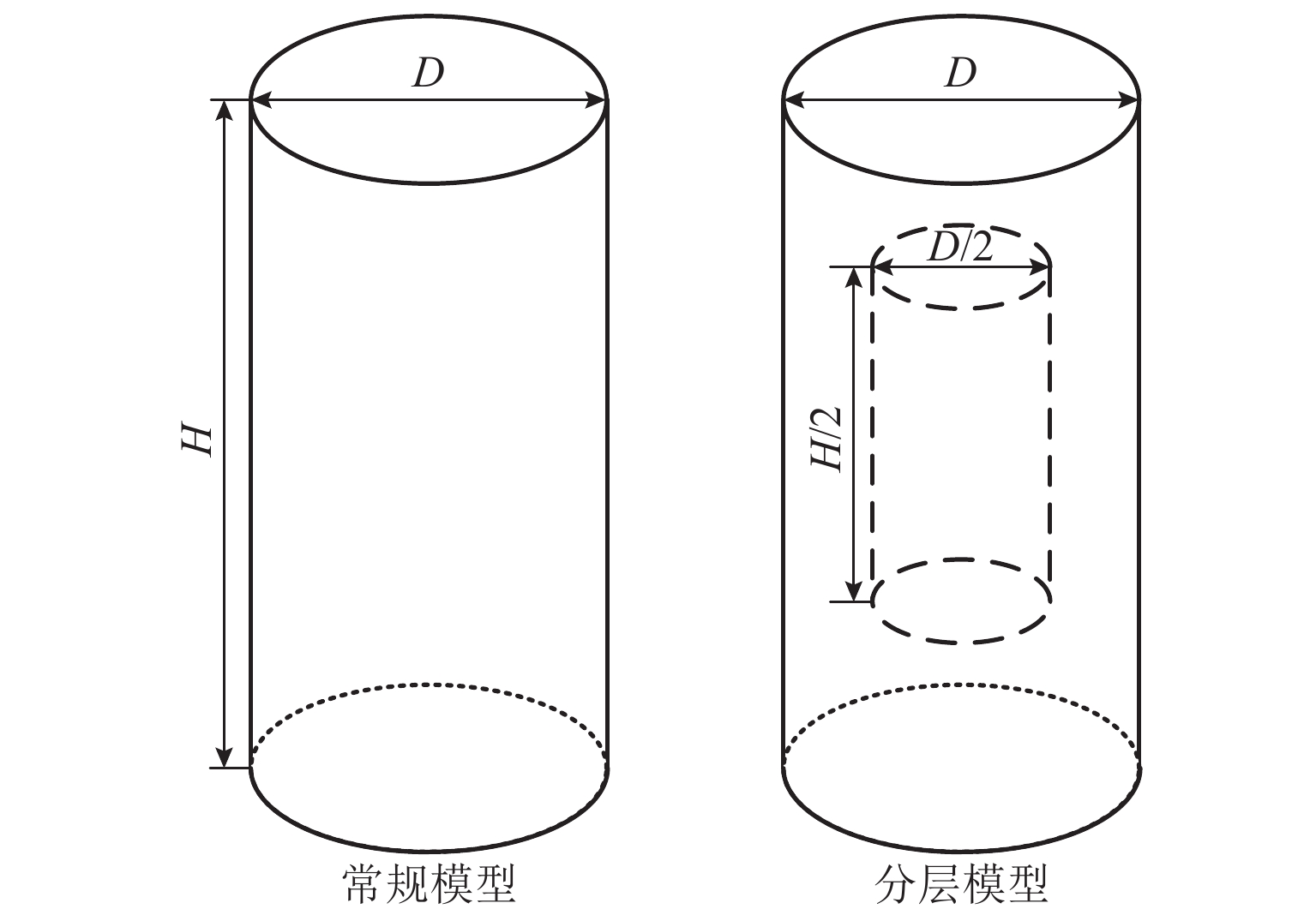
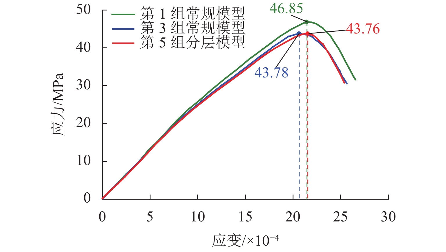
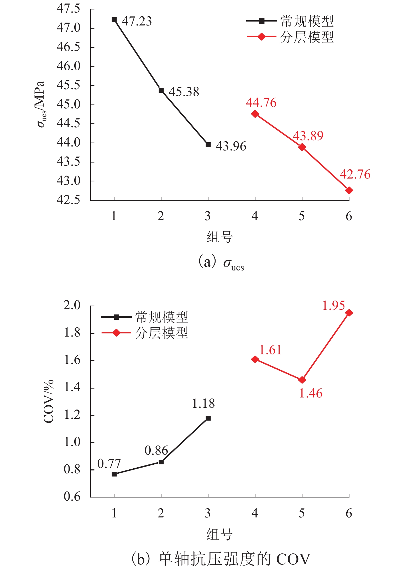
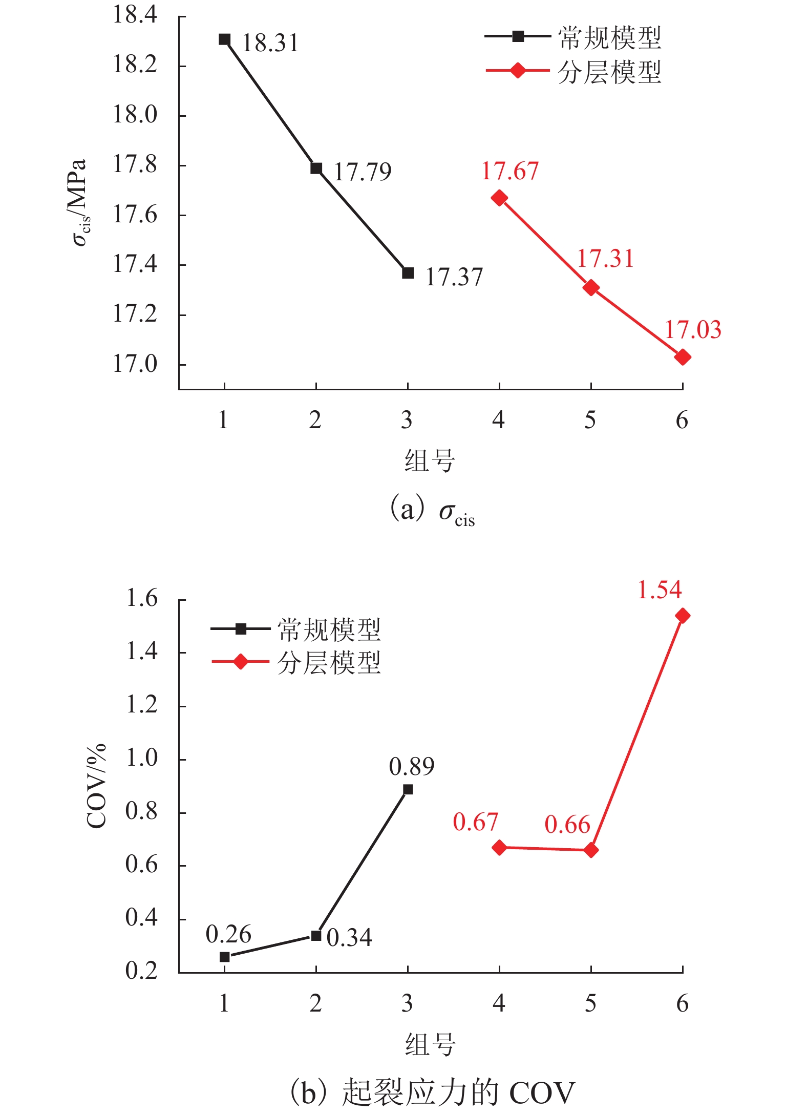
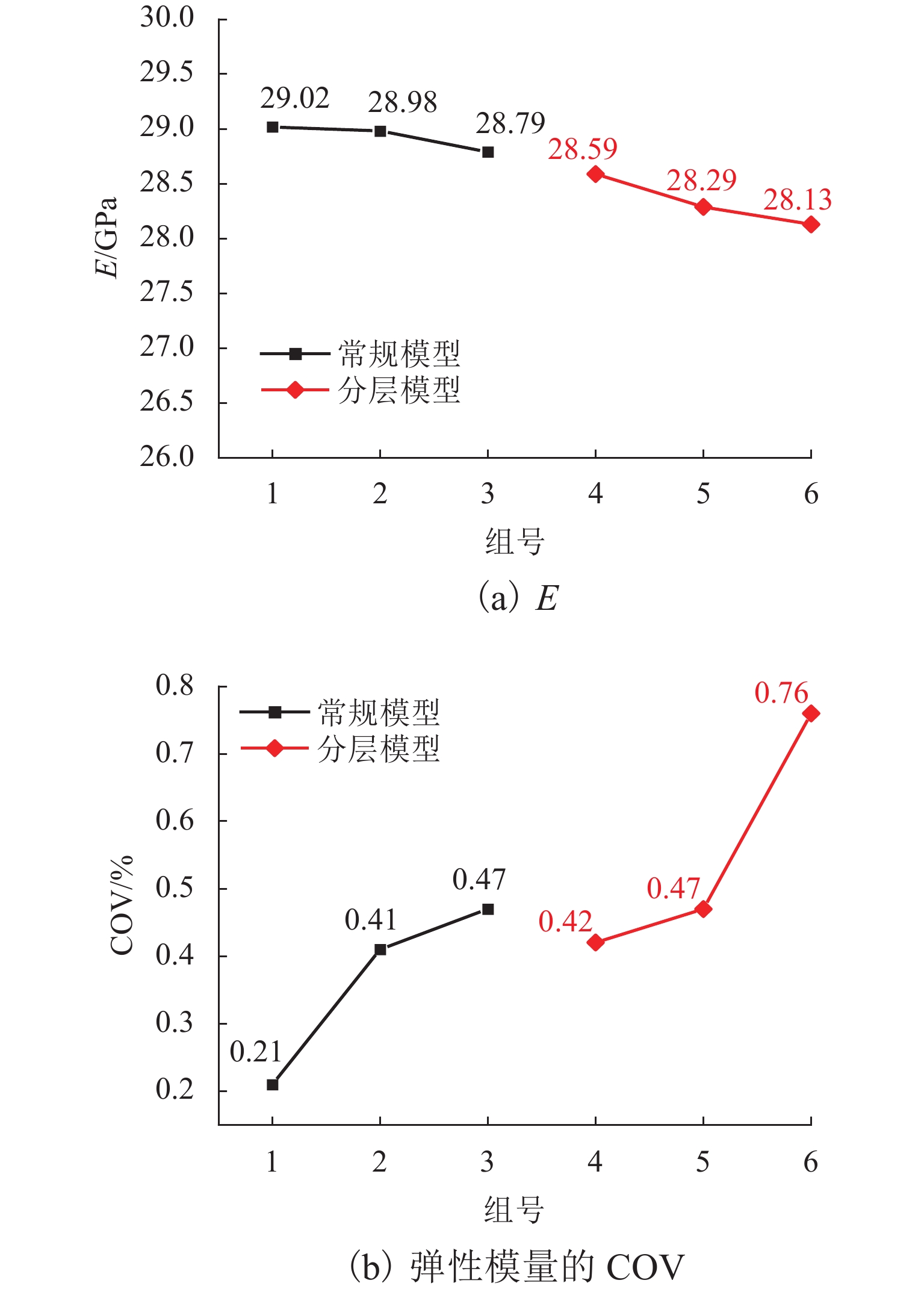
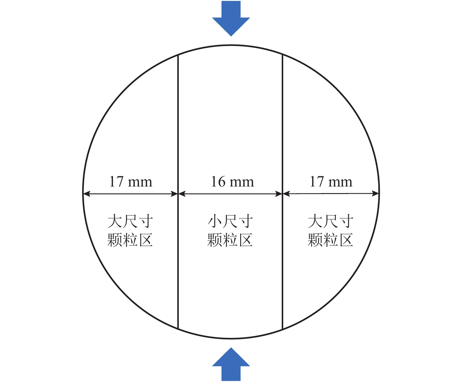
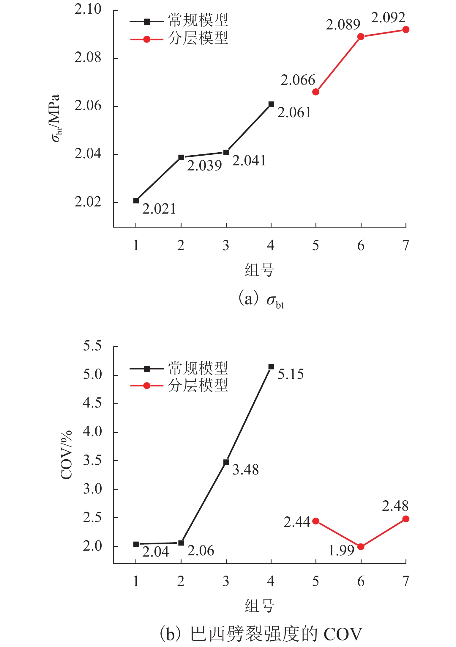
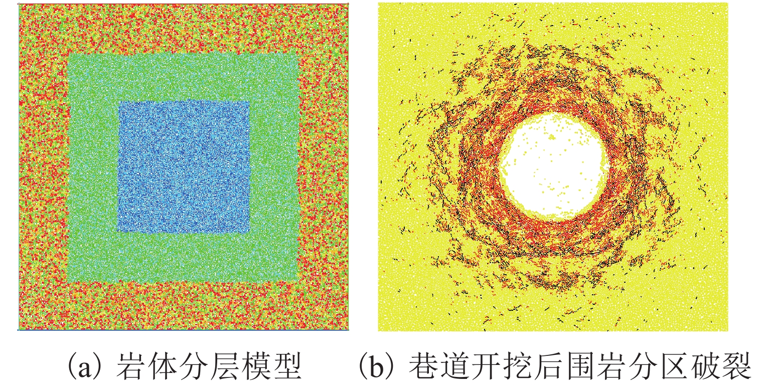
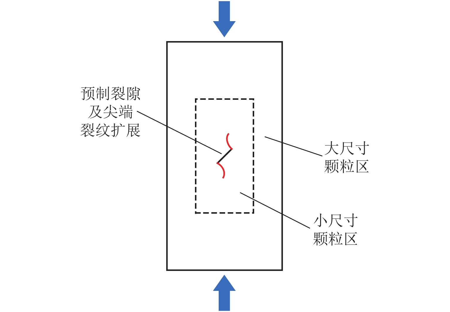
  • Discrete element analysis method is one of the important tools for studying rock mechanics behavior and refining the basic theory of rock mechanics. In order to improve the accuracy of the particle discrete element method to simulate indoor rock mechanics and large-scale engineering scale tests, a layered modeling method is proposed. This method adopts small-size particles for fine simulation of the rock or key rock mass area, and large-size particles for the outside area to expand the calculation area. The layered modeling method is used to carry out uniaxial compression and Brazilian splitting tests, and compared with the conventional modeling calculation results, which preliminarily verifies its feasibility to simulate indoor mechanical tests. The results show that the layered modeling method is affected by the particle size like conventional modeling, but it can reduce the number of particles in the particle flow code model and increase the calculation efficiency by more than 50%. The uniaxial compressive strength and crack initiation stress of the layered model are reduced by only 2.7% and 1.9% at most, compared with those of the conventional model with the corresponding outer layer. The coefficient of variation (COV) of uniaxial compressive strength and crack initiation stress is generally larger than that of the conventional model, but it is still within the acceptable range of 2%. The inhomogeneity of particle size distribution in the layered model has minor effect on the deformation properties of the model at the elastic stage, and the elastic modulus of the layered model is reduced by 1.3%−2.3% compared with the conventional model with the corresponding outer layer. The overall Brazilian splitting tensile strength of the layered model is increased by 1.32%−2.35% compared to that of the conventional model with the corresponding outer layer, and the macroscopic fracture characteristics are similar to those of the conventional small-particle model, but there are more cracks near the loading plate.


  • 磁悬浮技术具有无摩擦、微振动、长寿命及高精度等优点,被广泛地应用于高速机械领域. 磁轴承作为核心部件,一般与高速旋转电机配合用于高速旋转机械,如磁悬浮飞轮、磁悬浮控制力矩陀螺及磁悬浮电机等[1-3]. 对于直线运动,通常采用能够实现悬浮及导向功能的电磁铁与直线电机的组合,如磁浮列车、磁浮电梯等. 目前为止,世界很多国家已经对磁浮列车技术研究了较长时间,而且部分实现了商业运行,如中国、德国、日本、韩国等[4-6]. 磁浮列车由电磁铁与轨道功能件之间产生的电磁力支撑,从而实现无接触运行. 电磁铁为悬浮系统的核心执行部件,其电磁力特性决定了列车的承载能力,并与控制器、传感器相互配合实现列车的稳定悬浮. 尤其对于高速运行的磁浮列车,运行载荷更加复杂、苛刻,对承载能力及稳定性要求更高. 因此,电磁力特性分析作为基础研究,对悬浮系统的设计及优化起至关重要作用[7-9].

    目前,电磁力建模分析方法主要包含等效磁路法(EMC)及有限元法(FEM),其中,FEM计算精度较高,但效率较低,很难与控制模型联合用于分析系统实时特性. EMC计算速度较高,能够与控制模型联合用于系统实时动态特性分析,但其计算精度较低. 因此,在传统EMC模型中通常会考虑加入补偿系数,通过调整系数校正电磁力结果,使其与FEM结果接近[10-11]. 然而,传统EMC模型仅考虑线性工作区,导磁材料采用恒定的相对磁导率,忽略磁饱和影响,甚至忽略导磁材料磁阻. 这样会导致EMC模型结果在小电流区间内较准确,而在大电流区间就会出现较大偏差[12-13]. 本文在搭建高速磁浮悬浮电磁铁EMC模型时,考虑了导磁材料的磁阻及其非线性. 通过导磁材料B-HB为磁感应强度;H为磁场强度)曲线的拟合及引入,求解电磁力的准确性大幅度提高,适用范围增加.

    高速磁浮列车的悬浮电磁铁共有12个磁极,极性为NS交替,相邻磁极之间通过磁轭连接,磁场经过长定子铁芯形成回路,磁极与长定子之间的磁场产生电磁吸力,实现悬浮功能. 12个磁极分为左、右两组,分别由两个悬浮控制器单独控制,从而形成两个控制回路,每个回路对应两个间隙传感器. 传感器实时监测电磁铁与长定子之间的间隙,并反馈给悬浮控制器,经过控制策略计算,悬浮控制器输出相应电压给悬浮电磁铁,实现动态稳定悬浮.

    悬浮电磁铁与长定子的物理模型如图1所示. 其中电磁铁分为左、右两个回路单独控制,为简化计算模型,仅对半个电磁铁进行建模,并忽略两个回路间磁场的影响. 搭建的等效磁路模型如图2所示,磁路中包含了气隙磁阻、漏磁磁阻及导磁材料磁阻. 图中:Raj为磁极与长定子间的气隙磁阻;Rsi为长定子铁芯磁阻;Rei为磁极铁芯及磁轭磁阻;Rli为相邻磁极之间的漏磁磁阻;ϕajϕsiϕeiϕli分别为磁阻RajRsiReiRli对应的磁通;ϕpj 为磁极磁通;θj为磁极磁动势nIn为磁极匝数,I为控制回路电流;i=1,2,…,5,j=1,2,…,6.

    图  1  悬浮电磁铁及长定子模型
    Figure  1.  Model of maglev electromagnet and long stator
    图  2  半悬浮电磁铁等效磁路
    Figure  2.  EMC of half-maglev magnet

    根据建模需求,定义磁通、磁动势向量为

    {ϕ=(ϕ1,ϕl1,ϕ2,ϕl2,,ϕ5,ϕl5)T,ϕs=(ϕ1,ϕ2,,ϕ5)T,ϕa=(ϕ1,ϕ1+ϕ2,,ϕ4+ϕ5,ϕ5)T,ϕe=(ϕ1+ϕl1,ϕ2+ϕl2,,ϕ5+ϕl5)T,ϕp=(ϕ1+ϕl1,ϕ1+ϕl1+ϕ2+ϕl2,,ϕ4+ϕl4+ϕ5+ϕl5,ϕ5+ϕl5)T,θ=(θ1,θ2,,θ6)T.
    (1)

    磁极磁通向量ϕp与磁通向量ϕ的转换关系为

    ϕp =Tϕ

    式中:

    T=[11111111111111111111].

    在等效磁路中,根据基尔霍夫电压定律,建立关于磁通的方程组,如式(3).

    {Ra(j1)ϕa(j1)+Rsiϕsi+Rajϕaj+Reiϕei=θj1+θj,Rliϕli+Reiϕei=θj1+θj,
    (3)

    式中:j=2,3,,6.

    将式(1)表达为矩阵及向量形式为

    Aϕ=TTθ=TTnI
    (4)

    式中:向量n=(n, n, n, n, n, nTA为磁阻矩阵,AR10×10

    A=[Ra1+Ra2+Rs1+Re1Re1Ra200Re1Rl1+Re1000Ra20Ra2+Ra3+Rs2+Re2Re2Ra300Re2Rl2+Re20].

    1) 磁极与长定子间气隙磁阻

    受磁极直线发电机(linear generator, LIG)槽与长定子齿槽结构的影响,磁极与长定子之间的气隙磁通分布较为复杂,如图3所示. 因此,将气隙磁通等效分为主磁通、槽磁通及LIG磁通,分别对应3种磁阻.

    图  3  气隙磁场分布
    Figure  3.  Magnetic field distribution of air gap

    气隙磁阻为3种磁阻并联,即

    1Raj=1Ra,mj+1Ra,nj+1Ra,Lj,
    (5)

    式中:Ra,mj为主磁通对应的磁阻;Ra,nj为槽磁通对应的磁阻;Ra,Lj为LIG磁通对应的磁阻.

    每种磁阻可由式(6)计算.

    Ra,oj=sj+hojμ0Aa,oj,o[m,n,L]
    (6)

    式中:sj为磁极与长定子齿之间的间隙;μ0为空气磁导率;Aa,oj为相应气隙面积;hoj为额外气隙长度;m、n、L分别对应主磁通、槽磁通和LIG磁通.

    2) 相邻磁极间漏磁磁阻

    磁极磁通大部分经过长定子回到相邻磁极,小部分未经过长定子而直接回到相邻磁极,该部分磁通为相邻磁极之间的漏磁,对应的磁阻称为漏磁磁阻,可由式(7)计算.

    Rli=hliμ0Ali
    (7)

    式中:Ali为等效气隙面积;hli为相邻磁极间的等效气隙长度.

    3) 导磁材料磁阻

    对于长定子铁芯、磁极铁芯及磁轭的磁阻,采用分段方式进行求解,且尽可能保证每段的截面积相同. 具体分段如图4所示,其中,磁极及磁轭共分为5段(1~5),长定子分为3段(6~8). 该部分磁阻计算时考虑导磁材料的非线性.

    图  4  铁芯的分段
    Figure  4.  Iron core sections

    磁极铁芯及磁轭磁阻为

    Rei=5k=1lei,kμ0μr(ϕei,k)Aei,k
    (8)

    长定子铁芯磁阻为

    Rsi=8k=6lsi,kμ0μr(ϕsi,k)Asi,k,
    (9)

    式(8)、(9)中:lei,k, lsi,k分别为悬浮电磁铁侧、长定子侧每段铁芯的长度;Aei,k, Asi,k分别为悬浮电磁铁侧、长定子侧每段铁芯的截面积;μr为每段铁芯的相对磁导率;ϕsi,k为第i个磁回路中第k段长定子内的磁通量;ϕei,k为第i个回路中第k段磁极铁芯或磁轭内的磁通量.

    为在EMC模型中引入导磁材料的非线性,不再将μr简单地设置为恒定值,而是根据每段铁芯的磁通进行计算. 磁极铁芯、磁轭及长定子铁芯均采用硅钢片,牌号为M530-50A,导磁材料的非线性可通过B-H曲线体现,如图5所示.

    图  5  铁芯B-H曲线- M530-50A
    Figure  5.  B-H curve of iron core-M530-50A

    根据文献[14],B-H曲线可采用式(10)函数进行拟合.

    H=α1B+α2Bα3,
    (10)

    式中:α1α2α3为拟合函数自变量B的系数,可通过对图5B-H曲线的拟合确定.

    长定子铁芯的相对磁导率可表示为

    μr1=Bμ0H=1μ0(α1+α2Bα31).
    (11)

    根据磁密、面积及磁通的关系,式(11)可表达为

    μr1=1μ0(α1+α2(ϕsiAsi,k)α31).
    (12)

    同理可求解磁极铁芯及磁轭的相对磁导率为

    μr2=1μ0(α1+α2(ϕeiAei,k)α31).
    (13)

    将式(12)、(13)代入式(8)、(9)求解磁极铁芯、磁轭及长定子铁芯磁阻. 通过式(5)~(9)可知,磁阻矩阵A与间隙s及磁通ϕ相关,因此,将其记为As,ϕ).

    悬浮电磁铁分为两个控制回路,分别由一个控制器进行供电. 控制器的输出为电压,根据控制回路的负载特性转变为相应的负载电流. 在进行电磁力模型与控制模型联合分析时,需要搭建电磁铁的电路模型,其功能是将控制模型的输入电压转变为负载电流,再结合EMC模型计算电磁力. 与EMC模型类似,仅搭建一个回路的模型,6个磁极串联实际可等效为6个电阻与6个电感的串联,如图6所示. 图中:RMj为单个磁极电阻;LMj为单个磁极电感;ULj为单个磁极电感电压;UM为单个控制回路的输入电压.

    图  6  悬浮电磁铁控制回路
    Figure  6.  Control loop of maglev electromagnet

    根据电路模型,单个控制回路的输入电压为

    UM=RMI+6j=1ULj=RMI+nTϕp,
    (14)

    式中:RM为单个控制回路的总电阻.

    整理式(14),控制回路电流可表达为

    I=(UMnTϕp)/RM.
    (15)

    式(4)给出了磁通与电流关系,式(15)给出了磁通、电流与电压关系. 将式(15)代入式(4),可得磁通与电压的关系为

    A(s,ϕ)ϕ=TTn(UMnTϕp)/RM.
    (16)

    根据磁通关系ϕp=Tϕ,式(16)整理为

    TTnnTTϕ = TTnUMRMA(s,ϕ)ϕ.
    (17)

    经过计算发现,矩阵TTnnTT为奇异矩阵,常微分式(17)很难进行求解. 因此,为便于求解方程,采用中间变量替换原变量.

    根据磁通关系ϕp=Tϕ,将式(16)整理成变量为ϕp的方程,如式(18)

    A(s,ϕ)T1ϕp=TTn(UMnTϕp)/RM.
    (18)

    进一步整理为

    nTϕp=nTTA1(s,ϕ)TTn(UMnTϕp)/RM.
    (19)

    将6个磁极的磁通之和β作为中间变量,则β可表示为

    β=6j=1ϕpj.
    (20)

    将式(20)代入式(19),得到关于β的常微分方程为

    nβ=nTTA1(s,ϕ)TTn(UMnβ)/RM,
    (21)

    式中:nTTA−1(s,ϕ)TTn不再是一个矩阵或向量,而是一个关于sϕ的变量,记为1/M (s,ϕ).

    对式(21)进行整理得

    ˙β=UM/nRMM(s,ϕ).
    (22)

    依据式(15)、(22),可得Iβ间的关系为

    I=nM(s,ϕ)β.
    (23)

    依据式(19)、(22)及磁通关系ϕp=Tϕ,得到ϕβ间的关系为

    ϕ=A1(s,ϕ)TTnM(s,ϕ)nβ.
    (24)

    通过式(22)~(24)计算出悬浮电磁铁电流以及电磁力求解所需的磁通.

    根据式(5),计算各部分气隙的磁通为

    ϕa,oj=ϕajRajRa,oj.
    (25)

    基于虚功原理,各部分气隙对应的电磁力为

    Fmag,oj=ϕ2a,oj2μ0Aa,oj.
    (26)

    单个磁极电磁力为式(26)中各部分电磁力之和,即

    Fmag,j=Fmag,mj+Fmag,nj+Fmag,Lj.

    最后,求解半个悬浮电磁铁的电磁力为

    Fmag=6j=1Fmag,j.

    根据电磁力解析过程,EMC模型可简化为图7所示的结构框图,输入为电压及间隙,输出为电流及电磁力. 首先进行磁阻计算,并组建磁阻矩阵,而导磁材料磁阻的计算需要将磁通作为输入. 采用磁阻矩阵A进行电流及磁通计算,磁通需通过常微分方程及代数方程求解,磁通求解结果一方面用于电磁力计算,一方面反馈给导磁材料磁阻计算.

    图  7  电磁力模型框图
    Figure  7.  Magnetic force model

    根据悬浮电磁铁及长定子的尺寸及参数(如表1所示),对本文EMC模型进行量化. 此外,将导磁材料的相对磁导率设为恒定值,搭建基于线性导磁材料的传统EMC模型. 对两个模型电磁力的计算结果进行对比分析,如图8所示.

    表  1  悬浮电磁铁及长定子参数
    Table  1.  Parameters of maglev electromagnet and long stator
    项点取值项点取值
    定子极距/mm258.0铁芯厚度/mm170.0
    电磁铁极距/mm266.5磁极匝数300
    定子齿宽度/mm43.0额定磁间隙/mm12.5
    定子槽宽度/mm43.0恒定相对磁导率7 000
    下载: 导出CSV 
    | 显示表格
    图  8  线性与非线性材料EMC电磁力
    Figure  8.  Electromagnetic forces of EMC models with linear and nonlinear materials

    磁间隙为12.5 mm,电流在0~35 A内,两个模型的电磁力结果非常接近;当电流超过35 A时,随着电流增加,计算结果偏差增大. 原因是实际工作状态下,随着电流增大,导磁部件的磁密增大;当达到材料饱和磁密时,磁密随电流的增加率大幅降低,电磁力也相应地出现饱和现象,而传统EMC模型并未考虑材料的磁饱和. 因此,传统EMC模型适用于小电流区间,一般应用在工作点附近的线性区间20~30 A. 而大电流区间与实际工作情况不符,例如在故障、起浮、降落等特殊工况时,模型精度大幅降低,无法用于电磁力计算及系统特性分析.

    为验证本文提出的EMC模型准确性,搭建了悬浮电磁铁与长定子FEM模型,如图9所示,两者电磁力的计算结果如图10所示. 磁间隙12.5 mm与16.0 mm,电流0~80 A内,两者电磁力的计算结果具备非常高的一致性,均存在饱和现象;磁间隙12.5 mm,电流50 A时,电磁力偏差最大,EMC计算结果为115 kN,FEM计算结果为110 kN,偏差仅为4.5%,这表明了基于非线性材料的EMC模型具有较高的准确性.

    图  9  悬浮电磁铁及长定子有限元模型
    Figure  9.  FEM model of maglev electromagnet and long stator
    图  10  EMC与FEM电磁力结果
    Figure  10.  Electromagnetic force results of EMC and FEM

    针对高速磁浮电磁铁特性研究,搭建了地面试验平台,对悬浮电磁铁的静态电磁力进行测试,如图11所示. 试验台通过液压系统调整长定子与悬浮电磁铁的间隙;采用两路电源供电,但受最大输出电流限制,仅对0~50 A电流进行测试,步长为5 A;通过力传感器检测电磁铁与长定子间的电磁力. 磁间隙12.5 mm下电磁力的测试结果与EMC及FEM的计算结果对比如图12所示.

    图  11  悬浮电磁铁静态电磁力测试
    Figure  11.  Static electromagnetic force test of maglev electromagnet
    图  12  电磁力计算及测试结果
    Figure  12.  Electromagnetic force calculation and test results

    额定工况下,悬浮电磁铁的工作点:磁间隙为12.5 mm,电流为25 A,电磁力约为46 kN. 在工作点处,EMC、FEM及试验测试的电磁力结果几乎相同,在其他电流值下,电磁力结果偏差也极小,从而进一步验证了本文EMC模型以及所搭建FEM模型的准确性.

    本文基于非线性材料搭建了高速磁浮悬浮电磁铁的磁路、电路及磁力模型,将计算结果与传统EMC模型进行对比分析,并通过有限元及试验验证,通过对模型研究分析,得到以下结论:

    1) 搭建悬浮电磁铁EMC模型时,采用了非线性导磁材料,通过引入B-H曲线的拟合函数,将导磁材料的非线性及饱和特性体现在模型中.

    2) 无论小电流区,还是大电流区,本文EMC模型求解的电磁力均与实际情况接近,相比传统EMC模型,结果更加准确,适用范围更广.

    3) 本文EMC模型能够快速、准确地求解电磁力,且通过电路模型实现与控制模型的良好匹配,因此,可通过联合仿真对悬浮系统动态特性进行深入分析,为悬浮系统设计及参数优化提供了依据.

  • [1]
    CUNDALL P A. The measurement and analysis of acceleration on rock slopes[D]. London: University of London, 1971.
    [2]
    CUNDALL P A. UDEC—a generalized distinct element program for modelling jointed rock, peter cundall associates[R]. [S.l.]: European Research Office, 1980
    [3]
    CUNDALL P A, STRACK O D L. A discrete numerical model for granular assemblies[J]. Géotechnique, 1979, 29(1): 47-65.
    [4]
    ZHANG X P, WONG L N Y. Cracking processes in rock-like material containing a single flaw under uniaxial compression:a numerical study based on parallel bonded-particle model approach[J]. Rock Mechanics and Rock Engineering, 2012, 45(5): 711-737.
    [5]
    DUAN K, KWOK C Y, MA X. DEM simulations of sandstone under true triaxial compressive tests[J]. Acta Geotechnica, 2017, 12(3): 495-510. doi: 10.1007/s11440-016-0480-6
    [6]
    CAI M, KAISER P K. Numerical simulation of the Brazilian test and the tensile strength of anisotropic rocks and rocks with pre-existing cracks[J]. International Journal of Rock Mechanics and Mining Sciences, 2004, 41: 478-483. doi: 10.1016/j.ijrmms.2004.03.086
    [7]
    JIANG M J, LEROUEIL S, KONRAD J M. Insight into shear strength functions of unsaturated granulates by DEM analyses[J]. Computers and Geotechnics, 2004, 31(6): 473-489. doi: 10.1016/j.compgeo.2004.07.001
    [8]
    刘宁,张春生,褚卫江,等. 锦屏二级水电站深埋隧洞开挖损伤区特征分析[J]. 岩石力学与工程学报,2013,32(11): 2235-2241.

    LIU Ning, ZHANG Chunsheng, CHU Weijiang, et al. Excavation damaged zone characteristics in deep tunnel of Jinping Ⅱ hydropower station[J]. Chinese Journal of Rock Mechanics and Engineering, 2013, 32(11): 2235-2241.
    [9]
    李涛,朱连华,李彬如,等. 深基坑开挖土拱效应影响因素研究[J]. 中国矿业大学学报,2017,46(1): 58-65. doi: 10.13247/j.cnki.jcumt.000626

    LI Tao, ZHU Lianhua, LI Binru, et al. Study of the influence factors of soil arching effect for deep foundation pit excavation[J]. Journal of China University of Mining & Technology, 2017, 46(1): 58-65. doi: 10.13247/j.cnki.jcumt.000626
    [10]
    WU S C, CHEN L, CHENG Z Q. Macro and meso research on the zonal disintegration phenomenon and the mechanism of deep brittle rock mass[J]. Engineering Fracture Mechanics, 2019, 211: 254-268. doi: 10.1016/j.engfracmech.2019.02.023
    [11]
    刘春,乐天呈,施斌,等. 颗粒离散元法工程应用的三大问题探讨[J]. 岩石力学与工程学报,2020,39(6): 1142-1152. doi: 10.13722/j.cnki.jrme.2019.0977

    LIU Chun, LE Tiancheng, SHI Bin, et al. Discussion on three major problems of engineering application of the particle discrete element method[J]. Chinese Journal of Rock Mechanics and Engineering, 2020, 39(6): 1142-1152. doi: 10.13722/j.cnki.jrme.2019.0977
    [12]
    POTYONDY D O, CUNDALL P A. A bonded-particle model for rock[J]. International Journal of Rock Mechanics and Mining Sciences, 2004, 41(8): 1329-1364. doi: 10.1016/j.ijrmms.2004.09.011
    [13]
    YANG B D, JIAO Y, LEI S T. A study on the effects of microparameters on macroproperties for specimens created by bonded particles[J]. Engineering Computations, 2006, 23(6): 607-631. doi: 10.1108/02644400610680333
    [14]
    YOON J. Application of experimental design and optimization to PFC model calibration in uniaxial compression simulation[J]. International Journal of Rock Mechanics and Mining Sciences, 2007, 44(6): 871-889. doi: 10.1016/j.ijrmms.2007.01.004
    [15]
    DING X B, ZHANG L Y, ZHU H H, et al. Effect of model scale and particle size distribution on PFC3D simulation results[J]. Rock Mechanics and Rock Engineering, 2014, 47(6): 2139-2156. doi: 10.1007/s00603-013-0533-1
    [16]
    XU X L, WU S C, GAO Y T, et al. Effects of micro-structure and micro-parameters on Brazilian tensile strength using flat-joint model[J]. Rock Mechanics and Rock Engineering, 2016, 49(9): 3575-3595. doi: 10.1007/s00603-016-1021-1
    [17]
    POTYONDY D O. PFC3D flat joint contact model[R]. Minneapolis: ITASCA Consulting Group, 2013.
    [18]
    WU S C, XU X L. A study of three intrinsic problems of the classic discrete element method using flat-joint model[J]. Rock Mechanics and Rock Engineering, 2016, 49(5): 1813-1830. doi: 10.1007/s00603-015-0890-z
    [19]
    SUITS L D, SHEAHAN T C, FUENKAJORN K, et al. Laboratory determination of direct tensile strength and deformability of intact rocks[J]. Geotechnical Testing Journal, 2011, 34(1): 103134. doi: 10.1520/GTJ103134
    [20]
    MA J, WU S C, ZHANG X P, et al. Modeling acoustic emission in the Brazilian test using moment tensor inversion[J]. Computers and Geotechnics, 2020, 123: 103567. doi: 10.1016/j.compgeo.2020.103567
    [21]
    NAKASHIMA S, TAGUCHI K, MORITOSHI A, et al. Loading conditions in the Brazilian test simulation by DEM[C]//47th US Rock Mechanics/Geomechanics Symposium, American Rock Mechanics Association. San Francisco: [s.n.], 2013: 1833-1838.
    [22]
    XU X L, WU S C, JIN A B, et al. Review of the relationships between crack initiation stress, mode I fracture toughness and tensile strength of geo-materials[J]. International Journal of Geomechanics, 2018, 18(10): 04018136.1-04018136.20.
  • Relative Articles

    [1]WANG Zhijie, CHENG Biao, YANG Guangqing, GAO Gushun, WANG He. Mesoscopic Study on Mechanical and Deformation Behaviors of Reinforced Buried Pipelines Under Vertical Loads[J]. Journal of Southwest Jiaotong University, 2025, 60(1): 119-127. doi: 10.3969/j.issn.0258-2724.20230046
    [2]WANG Xuejun, YANG Hanxiong. Prediction of Discrete Element Breakage Parameter for Ballast Particles Based on Genetic Algorithm–Back Propagation Neural Network Model[J]. Journal of Southwest Jiaotong University. doi: 10.3969/j.issn.0258-2724.20240069
    [3]SHI Zengshu, LI Yao, GUO Jin, ZHANG Yadong. Testing Modeling Method for Engineering Testing of High-Speed Railway Signaling System[J]. Journal of Southwest Jiaotong University, 2024, 59(5): 1023-1033. doi: 10.3969/j.issn.0258-2724.20220674
    [4]KANG Jinsong, DING Hao, NI Fei, WANG Fengxiang. Modeling of High-Speed Maglev Linear Synchronous Motors Considering Influence of Suspension System[J]. Journal of Southwest Jiaotong University, 2024, 59(4): 729-736. doi: 10.3969/j.issn.0258-2724.20230431
    [5]CHEN Cheng, RAO Wenjin, LI Wenjun, ZHANG Lei, TANG Yuyan. Maintenance Mechanism of Ballast Tamping and Stone-Blowing Using Discrete Element Method[J]. Journal of Southwest Jiaotong University, 2024, 59(2): 256-263, 306. doi: 10.3969/j.issn.0258-2724.20220171
    [6]YIN Haipeng, LI Youtang, HUANG Hua. Modeling and Evaluation of Aggregate Based on Influence of Geometry Morphology[J]. Journal of Southwest Jiaotong University, 2022, 57(6): 1184-1192. doi: 10.3969/j.issn.0258-2724.20210770
    [7]LIU Junqi, ZHANG Zeqiang, GONG Juhua, ZHANG Yu. Modeling and Optimization Method of Constrained Corridor Allocation Problem[J]. Journal of Southwest Jiaotong University, 2022, 57(6): 1376-1385. doi: 10.3969/j.issn.0258-2724.20200803
    [8]WANG Jun, LIN Guojin, TANG Xie, XU Guowen, TANG Rui. Failure Characteristics and Engineering Application of Layered Rock with Two Pre-existing Non-coplanar Fissures[J]. Journal of Southwest Jiaotong University, 2020, 55(4): 719-725, 732. doi: 10.3969/j.issn.0258-2724.20180044
    [9]SUN Chaoyi, CHEN Congxin, ZHENG Yun, LU Zude, DENG Yangyang. Discussion on Slope Stability Analysis Method of Abandoned Dreg Site Based on Spatial Effect[J]. Journal of Southwest Jiaotong University, 2019, 54(1): 97-105. doi: 10.3969/j.issn.0258-2724.20170607
    [10]WANG Jun, LIN Guojin, TANG Xie, HE Chuan. Face Stability Analysis of Shield Tunnel in Sandy Ground Using 3D DEM[J]. Journal of Southwest Jiaotong University, 2018, 53(2): 312-321. doi: 10.3969/j.issn.0258-2724.2018.02.013
    [11]WU Yanbin, HUANG Fanglin. Refined Finite Element Modeling Methodof Spatial Prestressed Steel Beam[J]. Journal of Southwest Jiaotong University, 2017, 30(6): 1082-1087. doi: 10.3969/j.issn.0258-2724.2017.06.007
    [12]JING Guoqing, HUANG Hongmei, SHI Xiaoyi, CAI Xiaopei. Triaxial Test and DEM Analysis of Ballast Aggregate with Angularity Breakage[J]. Journal of Southwest Jiaotong University, 2017, 30(2): 216-221. doi: 10.3969/j.issn.0258-2724.2017.02.002
    [13]WANG Yusuo, LI Junjie, LI Zhenghui, FENG Gaofei, WU Hao, HE Junnan. Assessment of Rockfall Impact Force by Particle Flow Code Numerical Simulation Based on Discrete Element Model[J]. Journal of Southwest Jiaotong University, 2016, 29(1): 22-29. doi: 10.3969/j.issn.0258-2724.2016.01.004
    [14]DU Xin, ZENG Yawu, GAO Rui, YAN Jing, CAO Yuan. Effects of Particle Shape on Friction Mechanism Based on Discrete Element Method[J]. Journal of Southwest Jiaotong University, 2012, 25(2): 252-257. doi: 10.3969/j.issn.0258-2724.2012.02.014
    [15]ZHOU Lingyuan, LI Qiao. Updated Lagrangian Co-rotational Formulation for Geometrically Nonlinear FE Analysis of 3-D Beam Element[J]. Journal of Southwest Jiaotong University, 2006, 19(6): 690-695.
    [16]CHENXian-guo, WANG Xian-jun. 2D and 3D Finite Element Analyses of Overlapping Tunnels[J]. Journal of Southwest Jiaotong University, 2003, 16(6): 643-647.
    [17]SUGuo-shao, DUANHai-juan, YANLiu-bin. Mapped Infinite Element for Three-Dimensional Intercalations[J]. Journal of Southwest Jiaotong University, 2001, 14(2): 162-165.
    [18]TangHuaping, KongXiang an. A Recursive Formulation for the Dynamic Analysis of Open Loop Tree Deferrable Multibody Systems[J]. Journal of Southwest Jiaotong University, 1999, 12(3): 284-289.
  • Cited by

    Periodical cited type(2)

    1. 陈龙,何志敏,温时雨,吴顺川,贺尧. 离散元分层模型单轴压缩试验适用性宏细观分析. 矿业研究与开发. 2024(11): 118-127 .
    2. 孙孟,尤小梅,王剑松,李响. 基于插值法的粉煤灰离散元仿真参数标定. 成组技术与生产现代化. 2023(01): 26-31 .

    Other cited types(12)

  • Created with Highcharts 5.0.7Amount of accessChart context menuAbstract Views, HTML Views, PDF Downloads StatisticsAbstract ViewsHTML ViewsPDF Downloads2024-052024-062024-072024-082024-092024-102024-112024-122025-012025-022025-032025-04010203040
    Created with Highcharts 5.0.7Chart context menuAccess Class DistributionFULLTEXT: 48.2 %FULLTEXT: 48.2 %META: 46.4 %META: 46.4 %PDF: 5.3 %PDF: 5.3 %FULLTEXTMETAPDF
    Created with Highcharts 5.0.7Chart context menuAccess Area Distribution其他: 10.4 %其他: 10.4 %China: 0.1 %China: 0.1 %Seattle: 0.2 %Seattle: 0.2 %[]: 0.3 %[]: 0.3 %三亚: 0.1 %三亚: 0.1 %三明: 0.1 %三明: 0.1 %三门峡: 0.1 %三门峡: 0.1 %上海: 0.7 %上海: 0.7 %下莱茵: 0.1 %下莱茵: 0.1 %东京: 0.1 %东京: 0.1 %东莞: 0.5 %东莞: 0.5 %临汾: 0.2 %临汾: 0.2 %乌兰察布: 0.1 %乌兰察布: 0.1 %乌鲁木齐: 0.1 %乌鲁木齐: 0.1 %佳木斯: 0.1 %佳木斯: 0.1 %信阳: 0.1 %信阳: 0.1 %兰州: 0.4 %兰州: 0.4 %北京: 5.7 %北京: 5.7 %十堰: 0.4 %十堰: 0.4 %南京: 1.5 %南京: 1.5 %南宁: 0.5 %南宁: 0.5 %南通: 0.2 %南通: 0.2 %台州: 0.1 %台州: 0.1 %合肥: 0.7 %合肥: 0.7 %呼和浩特: 0.1 %呼和浩特: 0.1 %哈尔滨: 0.1 %哈尔滨: 0.1 %唐山: 0.1 %唐山: 0.1 %嘉兴: 0.1 %嘉兴: 0.1 %大兴安岭地区: 0.1 %大兴安岭地区: 0.1 %大同: 0.5 %大同: 0.5 %大连: 0.6 %大连: 0.6 %天津: 2.1 %天津: 2.1 %安庆: 0.1 %安庆: 0.1 %宣城: 0.7 %宣城: 0.7 %常州: 0.1 %常州: 0.1 %广州: 0.9 %广州: 0.9 %张家口: 2.1 %张家口: 2.1 %徐州: 0.6 %徐州: 0.6 %成都: 1.4 %成都: 1.4 %扬州: 1.3 %扬州: 1.3 %揭阳: 0.1 %揭阳: 0.1 %攀枝花: 0.1 %攀枝花: 0.1 %昆明: 0.4 %昆明: 0.4 %晋中: 0.2 %晋中: 0.2 %杭州: 0.6 %杭州: 0.6 %柳州: 0.2 %柳州: 0.2 %格兰特县: 0.1 %格兰特县: 0.1 %武汉: 2.2 %武汉: 2.2 %池州: 0.2 %池州: 0.2 %沈阳: 0.8 %沈阳: 0.8 %洛阳: 0.3 %洛阳: 0.3 %济南: 0.2 %济南: 0.2 %济宁: 0.2 %济宁: 0.2 %淄博: 0.2 %淄博: 0.2 %深圳: 0.3 %深圳: 0.3 %温州: 0.1 %温州: 0.1 %湖州: 0.1 %湖州: 0.1 %湘潭: 0.1 %湘潭: 0.1 %漯河: 3.3 %漯河: 3.3 %烟台: 0.1 %烟台: 0.1 %珀斯: 0.1 %珀斯: 0.1 %石家庄: 1.5 %石家庄: 1.5 %福州: 0.2 %福州: 0.2 %自贡: 0.1 %自贡: 0.1 %舟山: 0.1 %舟山: 0.1 %芒廷维尤: 16.1 %芒廷维尤: 16.1 %芝加哥: 0.4 %芝加哥: 0.4 %苏州: 0.6 %苏州: 0.6 %西宁: 28.8 %西宁: 28.8 %西安: 0.9 %西安: 0.9 %诺沃克: 0.1 %诺沃克: 0.1 %贵阳: 0.1 %贵阳: 0.1 %运城: 0.5 %运城: 0.5 %连云港: 0.1 %连云港: 0.1 %邯郸: 0.4 %邯郸: 0.4 %郑州: 0.6 %郑州: 0.6 %重庆: 0.6 %重庆: 0.6 %铜仁: 0.2 %铜仁: 0.2 %镇江: 0.2 %镇江: 0.2 %长春: 0.2 %长春: 0.2 %长沙: 3.5 %长沙: 3.5 %青岛: 0.5 %青岛: 0.5 %马鞍山: 0.5 %马鞍山: 0.5 %鹤壁: 0.1 %鹤壁: 0.1 %其他ChinaSeattle[]三亚三明三门峡上海下莱茵东京东莞临汾乌兰察布乌鲁木齐佳木斯信阳兰州北京十堰南京南宁南通台州合肥呼和浩特哈尔滨唐山嘉兴大兴安岭地区大同大连天津安庆宣城常州广州张家口徐州成都扬州揭阳攀枝花昆明晋中杭州柳州格兰特县武汉池州沈阳洛阳济南济宁淄博深圳温州湖州湘潭漯河烟台珀斯石家庄福州自贡舟山芒廷维尤芝加哥苏州西宁西安诺沃克贵阳运城连云港邯郸郑州重庆铜仁镇江长春长沙青岛马鞍山鹤壁

Catalog

    通讯作者: 陈斌, bchen63@163.com
    • 1. 

      沈阳化工大学材料科学与工程学院 沈阳 110142

    1. 本站搜索
    2. 百度学术搜索
    3. 万方数据库搜索
    4. CNKI搜索

    Figures(10)  / Tables(4)

    Article views(464) PDF downloads(53) Cited by(14)
    Proportional views
    Related

    /

    DownLoad:  Full-Size Img  PowerPoint
    Return
    Return